Wiring
Electrical interconnects and Nucleo pin assignments for the final robot
Wiring Overview
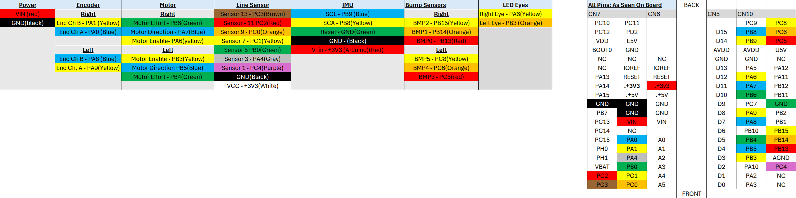
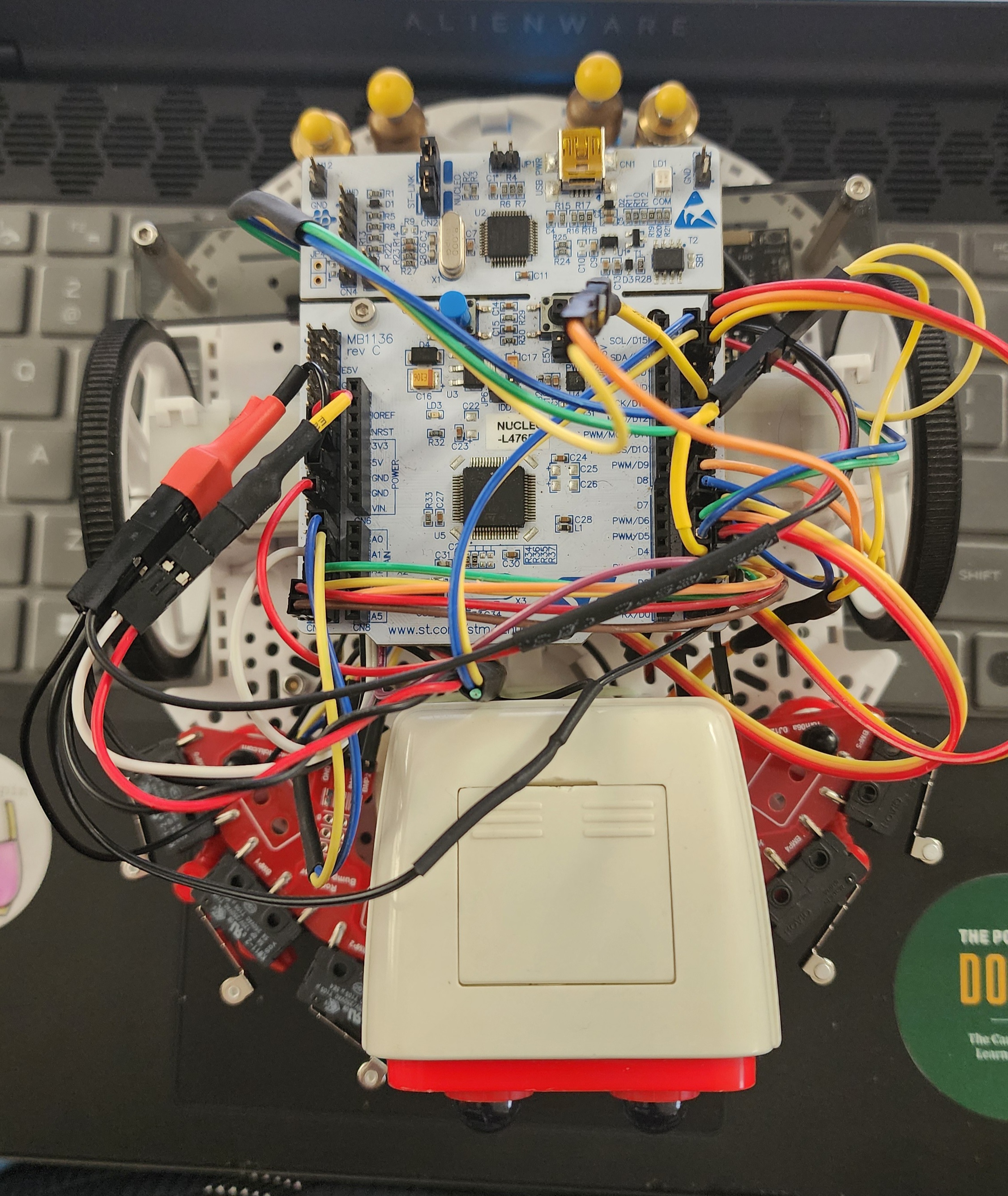
This page defines the electrical interconnects used on our Romi robot, including motor driver control, encoder feedback, reflectance sensing, inertial sensing, and bump-event inputs. The goal is to provide a single reference for connector-level wiring, Nucleo pin assignments, and the signals required by each subsystem in the final autonomous robot.
- Red wire
- Black wire
- Yellow wire
- Blue wire
- Green wire
- Orange wire
- Brown wire
- Gray wire
- Purple wire
- White wire
Nucleo Pin Constraints
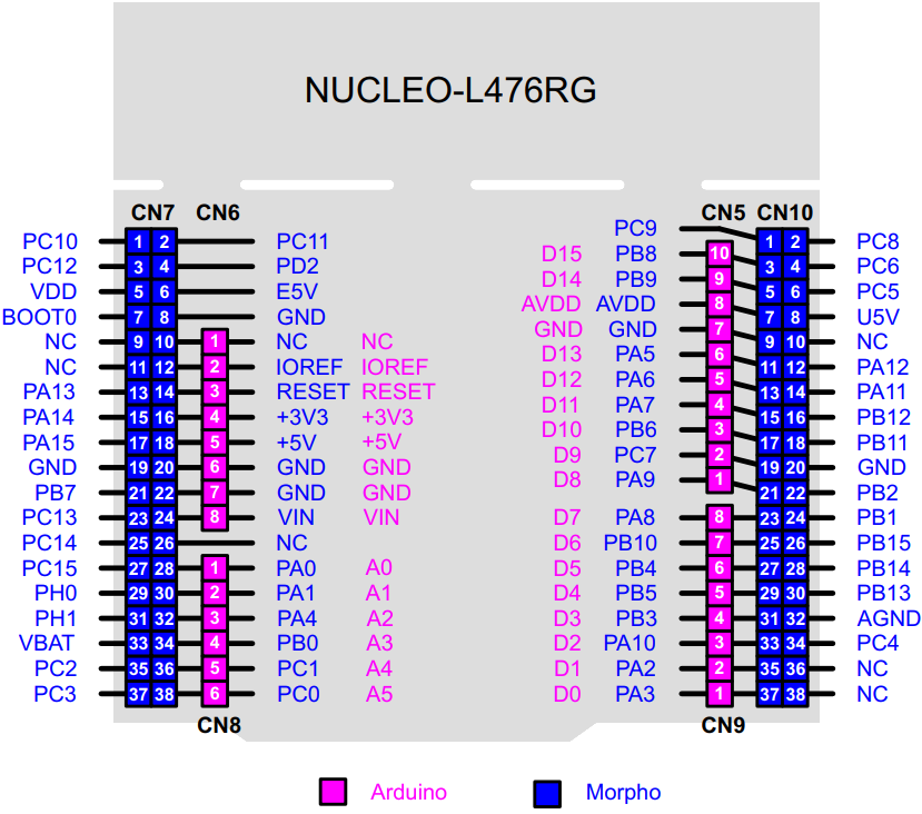
Several Nucleo pins were avoided because they are tied to onboard functions such as ST-Link communication, USB, SWD programming, the user button, the onboard LED, and the RTC oscillator. Avoiding these pins helped preserve reliable programming, debugging, and serial access during development and testing.
| Nucleo Pin | Arduino Label | Reserved Function |
|---|---|---|
| PA2 | A2 | UART link to ST-Link interface |
| PA3 | A3 | UART link to ST-Link interface |
| PA5 | A5 | Onboard user LED |
| PA11 | A11 | USB interface |
| PA12 | A12 | USB interface |
| PA13 | A13 | SWD programming interface |
| PA14 | A14 | SWD programming interface |
| PC13 | C13 | User button input |
| PC14 | C14 | 32 kHz RTC oscillator |
| PC15 | C15 | 32 kHz RTC oscillator |
Power
| Signal | Connection | Wire Color | Notes |
|---|---|---|---|
| VIN | VIN | Red | Main battery power input |
| GND | GND | Black | Common ground reference for the system |
Motor Control
The drivetrain used separate effort, direction, and enable lines for each motor. These connections supported closed-loop speed control and direction changes during line following, turning, and wall-response behaviors.
| Motor | Signal | Nucleo Pin | Wire Color |
|---|---|---|---|
| Right | Motor Effort | PB6 | Green |
| Right | Motor Direction | PA7 | Blue |
| Right | Motor Enable | PA6 | Yellow |
| Left | Motor Enable | PB3 | Yellow |
| Left | Motor Direction | PB5 | Blue |
| Left | Motor Effort | PB4 | Green |
Encoder Connections
Quadrature encoder feedback from both wheels was routed directly to the Nucleo so that the software could measure wheel speed and traveled distance for closed-loop motor control and state estimation.
| Encoder | Signal | Nucleo Pin | Wire Color |
|---|---|---|---|
| Right | Encoder Channel B | PA1 | Yellow |
| Right | Encoder Channel A | PA0 | Blue |
| Left | Encoder Channel B | PA8 | Blue |
| Left | Encoder Channel A | PA9 | Yellow |
IR Sensor Array
The line sensor array used seven analog reflectance channels. These signals were read by the controller to compute line position and steering error during centroid-based line following.
| Sensor Channel | Nucleo Pin | Wire Color | Notes |
|---|---|---|---|
| Sensor 13 | PC3 | Brown | Outer channel |
| Sensor 11 | PC2 | Red | Outer-mid channel |
| Sensor 9 | PC0 | Orange | Mid channel |
| Sensor 7 | PC1 | Yellow | Center channel region |
| Sensor 5 | PB0 | Green | Center channel region |
| Sensor 3 | PA4 | Gray | Inner channel |
| Sensor 1 | PC4 | Purple | Outer channel |
| Sensor GND | GND | Black | Sensor ground |
| Sensor VCC | +3V3 | White | Sensor supply voltage |
IMU Connections
The BNO055 IMU was connected over I2C and powered from the 3.3 V rail. This interface provided heading information used during turning actions and observer-based state estimation.
| IMU Signal | Nucleo Pin / Connection | Wire Color | Notes |
|---|---|---|---|
| SCL | PB9 | Blue | I2C clock |
| SDA | PB8 | Yellow | I2C data |
| Reset / Ground tie | GND | Green | Ground-related reset connection shown in the board table |
| GND | GND | Black | Ground reference |
| VIN | +3V3 | Red | 3.3 V supply from the controller |
Bump Sensors
Left and right bumper switch assemblies were connected as grouped digital inputs. These signals were used by the navigation task to detect wall contact and trigger backing-up and recovery behaviors.
| Side | Board Pin | Nucleo Pin | Wire Color |
|---|---|---|---|
| Right | BMP2 | PB15 | Yellow |
| Right | BMP1 | PB14 | Orange |
| Right | BMP0 | PB13 | Red |
| Left | BMP5 | PC8 | Yellow |
| Left | BMP4 | PC6 | Orange |
| Left | BMP3 | PC5 | Red |
Wiring Diagram and Full Assembly