Hardware
Physical platform, sensing stack, and embedded control hardware
Hardware Summary
This page summarizes the physical hardware stack used to build our Romi robot for the ME405 final project, with emphasis on the components that directly supported reliable line sensing, repeatable closed-loop motion, and autonomous obstacle-course navigation. Our final system combined a differential-drive mobile base with embedded control hardware, inertial sensing, line sensing, bump sensing, and supporting interface electronics so that the robot could make navigation decisions from real sensor measurements rather than open-loop assumptions alone.
Chassis and Drivetrain
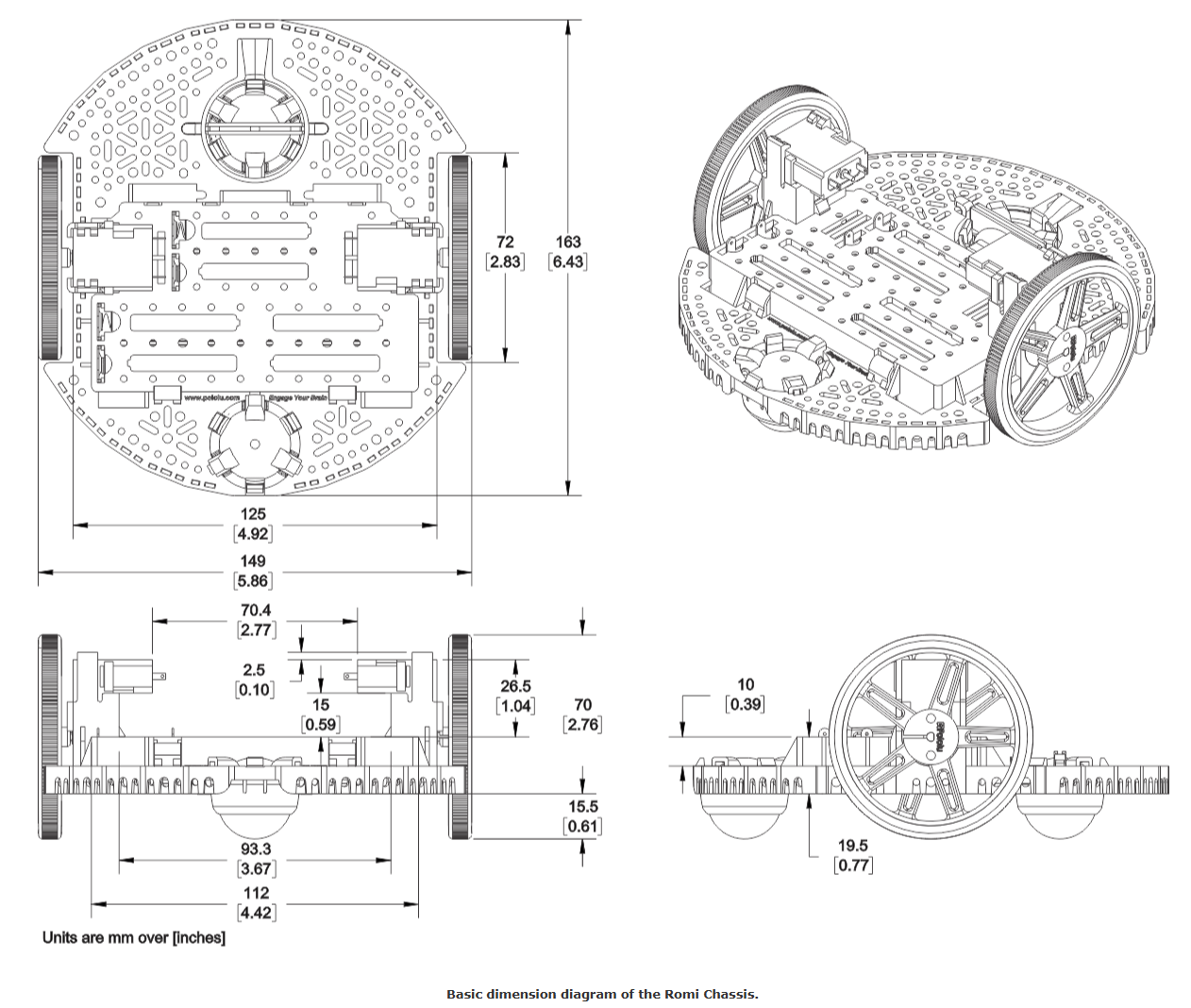
Our robot used a Pololu Romi differential-drive chassis as the mechanical foundation of the system. This platform integrates the main structure, drive motors, wheels, and encoders into a compact and repeatable base that is well suited for embedded motion control. For our project, the drivetrain provided the physical basis for closed-loop velocity control, distance-based maneuvers, and heading estimation during line following and turning.
| Parameter | Value | Notes |
|---|---|---|
| Wheel radius | 0.035 m | Used for distance and velocity estimation from wheel motion |
| Track width | 0.141 m | Used for heading and turning kinematics |
| Encoder resolution | 1437.1 ticks/rev | Used to convert encoder counts into wheel rotation and displacement |
| Hardware | Technical role in the system |
|---|---|
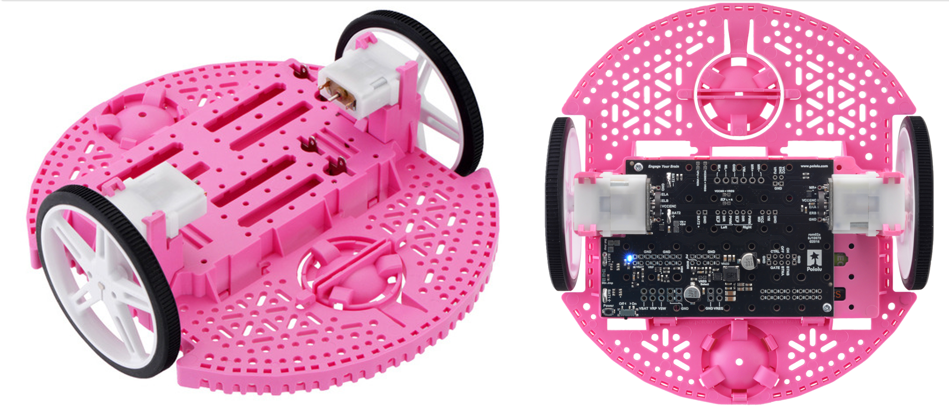
| Romi chassis and power distribution | Mechanical structure and integrated support for embedded electronics and wiring |
| DC gearmotors | Bidirectional actuation through PWM effort control |
| Quadrature encoders | Wheel position and speed feedback for closed-loop control and estimation |
| Wheels and caster | Ground interface that defines traction, mobility, and kinematic scaling |
Power Distribution Board
The power distribution board served as the electrical hub of the robot by routing battery power to the drivetrain and controller hardware while providing a consistent ground reference for the rest of the system. In practice, this simplified bring-up and troubleshooting by reducing wiring clutter and centralizing the main power connections used during repeated testing and final competition runs.
| Item | Technical role in the system |
|---|---|
| Battery input and distribution | Routes supply power to the motors and control electronics |
| Ground reference distribution | Provides a common return path for digital, analog, and actuation subsystems |
| Modular connection points | Simplifies inspection, rework, and repeated hardware iteration |
Microcontroller Board
The embedded compute core of the robot was an STM32 Nucleo L476RG board running MicroPython. This controller executed the cooperative task architecture used throughout the project and provided the timers, PWM outputs, GPIO, ADC channels, and serial interfaces needed for motor control, encoder measurement, line sensing, bump sensing, and IMU communication.
| Peripheral | Application in this project |
|---|---|
| Timers and PWM | Motor effort generation and timing support for periodic task execution |
| Encoder timers | Quadrature counting for wheel position and speed measurement |
| ADC inputs | Used for analog line-sensor measurements |
| UART / serial | User interface, debugging, and tuning feedback during testing |
| I2C | Communication with the BNO055 IMU |
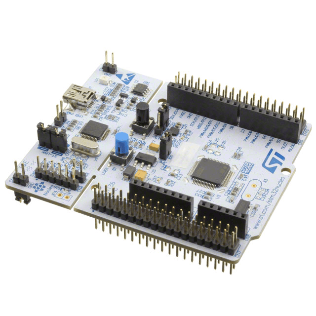
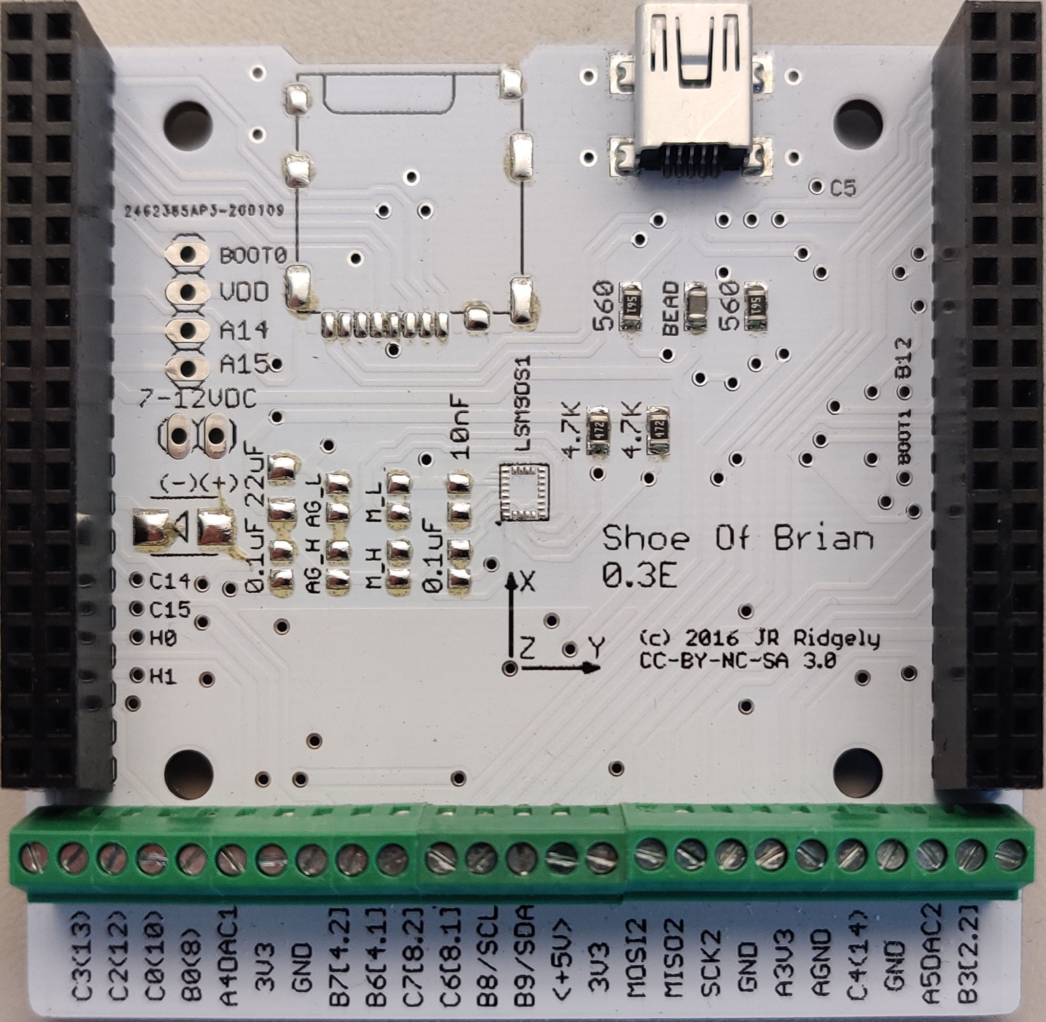
Shoe of Brian Interface Board
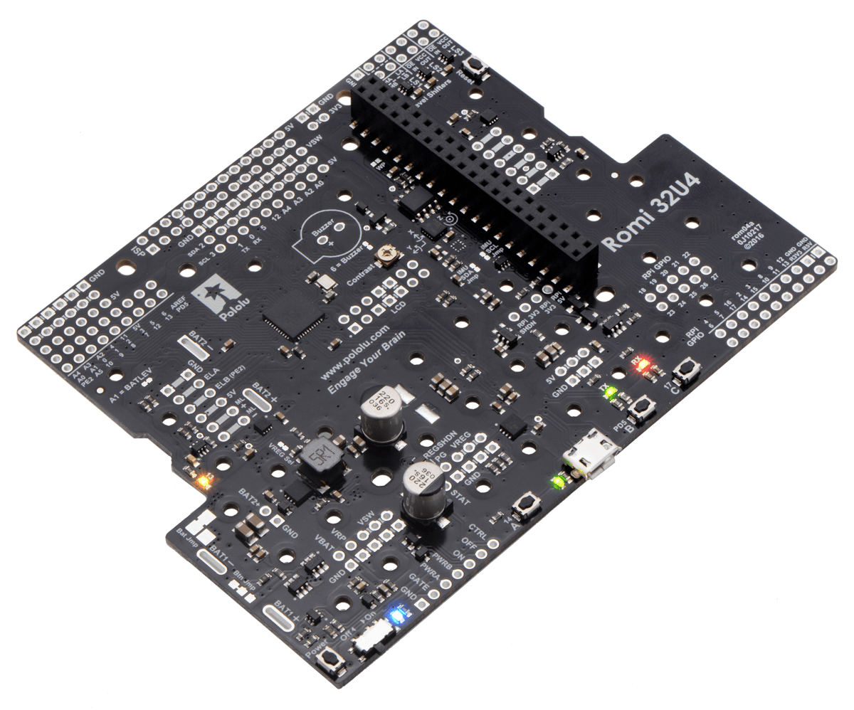
The modified Shoe of Brian board expanded the Nucleo into a more usable robotics interface by providing structured breakout connections for sensors, motors, and supporting wiring. In our build, this board reduced wiring complexity, improved signal organization, and made it easier to connect the Romi drivetrain, IMU, line sensor, and bump switches without rewiring the controller directly every time the layout changed.
| Feature | Purpose |
|---|---|
| Structured header breakout | Clean signal routing to motors, encoders, sensors, and communication hardware |
| Shared ground distribution | Stable electrical reference for mixed analog and digital subsystems |
| Rapid reconfiguration | Supports changes to pin mapping and wiring during iterative development |
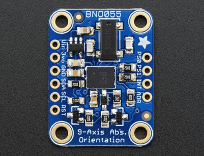
IMU
A BNO055 inertial measurement unit provided heading information for turning control, state estimation, and general motion awareness during the course. In our project, the IMU was especially useful during state-based turning actions and in the observer-based estimator, where heading measurements were used alongside encoder data to improve navigation behavior.
| Item | Value | Notes |
|---|---|---|
| Sensor | BNO055 | 9-axis IMU with onboard fusion support |
| Bus | I2C | Connected to the microcontroller through SCL and SDA lines |
| I2C address | 0x28 | Default initialization address used in the project |
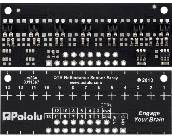
Line Sensor
A Pololu QTRX-MD-07A reflectance sensor array provided the main line-following signal for the robot. This sensor measured the reflectance profile beneath the front of the robot and allowed the software to compute a centroid-style tracking error for steering correction. Because line following was the dominant navigation mode on the course, the mounting height and alignment of the sensor were treated as important design parameters in order to keep the reflectance geometry consistent across runs.
| Hardware | Technical role in the system |
|---|---|
| QTRX-MD-07A reflectance array | Measures surface reflectance for line detection and lateral tracking error |
| Front mounting bracket / stand-off arrangement | Maintains repeatable sensor height and alignment relative to the floor |
Bump Sensor
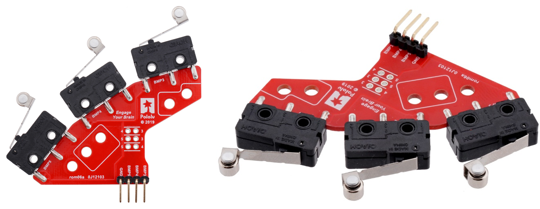
Left and right bumper switch assemblies provided event-based contact detection for wall interaction and recovery behavior. These bump sensors were placed at the front of the robot so that a collision with the wall could be detected cleanly before the line sensor or other front hardware was damaged. In the navigation logic, bumper activation was used as a direct trigger for backing up and transitioning into the next maneuver.
| Hardware | Technical role in the system |
|---|---|
| Left and right bumper switch assemblies | Discrete contact-triggered event inputs for collision detection and recovery logic |
| Front-mounted trigger geometry | Ensures reliable wall contact sensing before sensitive front hardware is impacted |